Structure of a WiFi frame (well, 802.11 specifically):
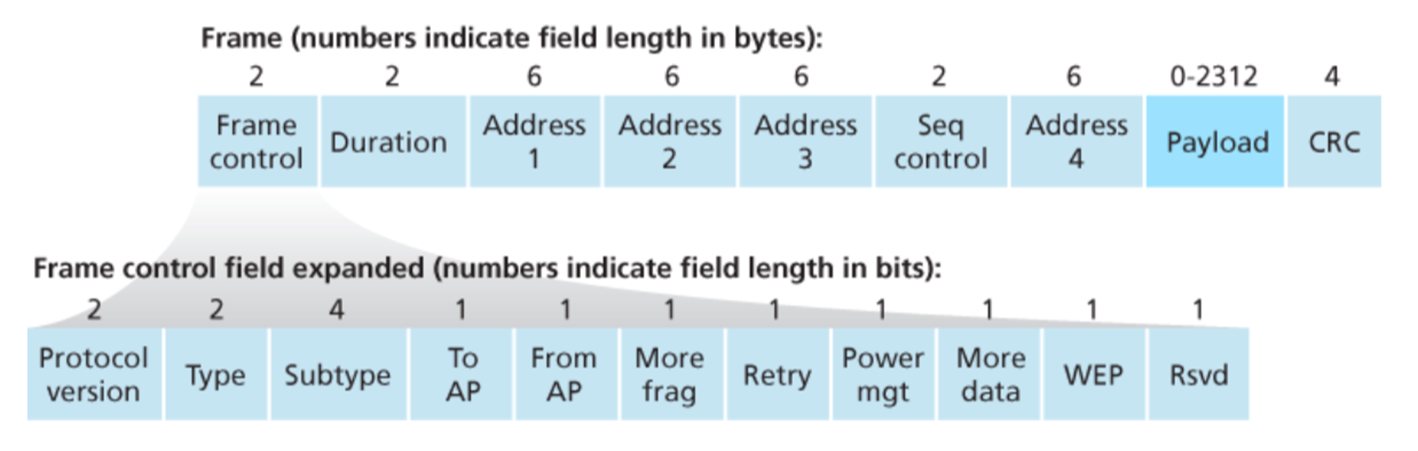
Address Fields
Address fields are interpreted differently based on the ToDS and FromDS bits in the frame’s Control field (above, it’s the very first field)
- In ad-hoc mode (one node is sending directly to another), both
DSbits are 0:- Address 1 is target node
- Address 2 is source node
- BSS ID
- When AP is sending to host in infrastructure mode,
ToDSis 0 andFromDSis 1:- Destination
- BSS ID
- Sender address
- When host is sending to AP in infrastructure mode,
ToDSis 1 and - When both
DSbits are 1- Ultimate destination
- Immediate sender
- Immediate destination
- Original source
TODO what's in the book doesn't match the slides!
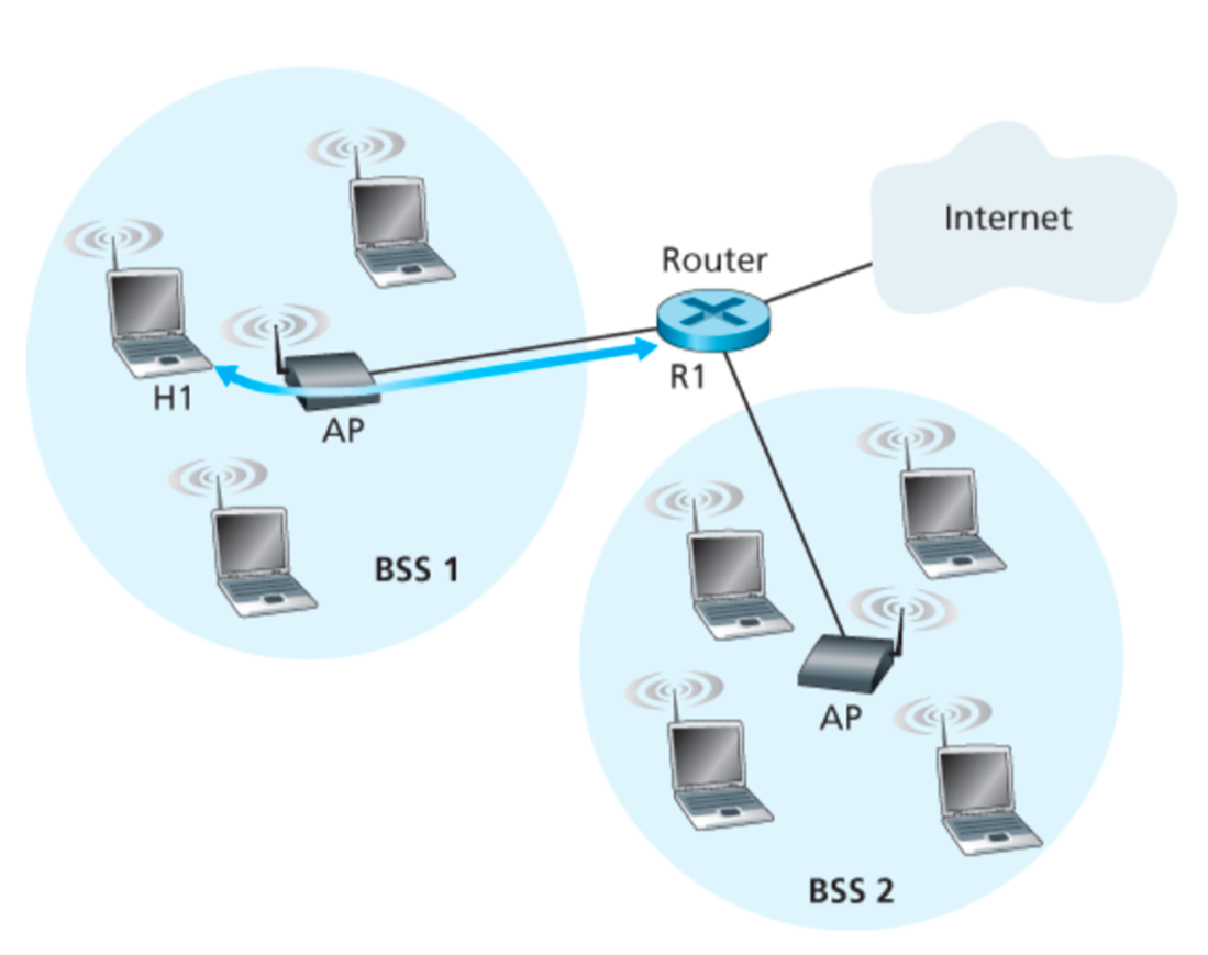
Case 1: Router R1 sends data to host H1
- R1 knows H1’s IP address, runs ARP to get MAC address
- R1 encapsulates the data in Ethernet frame
- Source address: R1’s MAC address
- Destination address: H1’s MAC address
- AP converts the Ethernet frame to WiFi frame
- Address 1: H1’s MAC address
- Address 2: AP’s MAC address
- Address 3: R1’s MAC address
- H1 can determine that the frame has come from R1 by checking the Address 3 field
Case 2: Host H1 responds by sending packet to router R1
- H1 creates a WiFi frame
- Address 1: AP’s MAC address
- Address 2: H1’s MAC address
- Address 3: R1’s MAC address
- AP can determine that the frame should be forwarded to R1 by checking Address 3 field
- AP converts the WiFi frame to Ethernet frame
- Source address: H1’s MAC address
- Destination address: R1’s MAC address